



























LED Semaphore Indicator Selection: What Electrical Panel Builders Should Know
Electrical panels are designed to bring important control and monitoring information together in one place. In substations and power distribution facilities, operators often need to check the displayed status of several switching devices without inspecting each component individually. A well-planned visual indication system can make this information easier to understand during everyday operations.

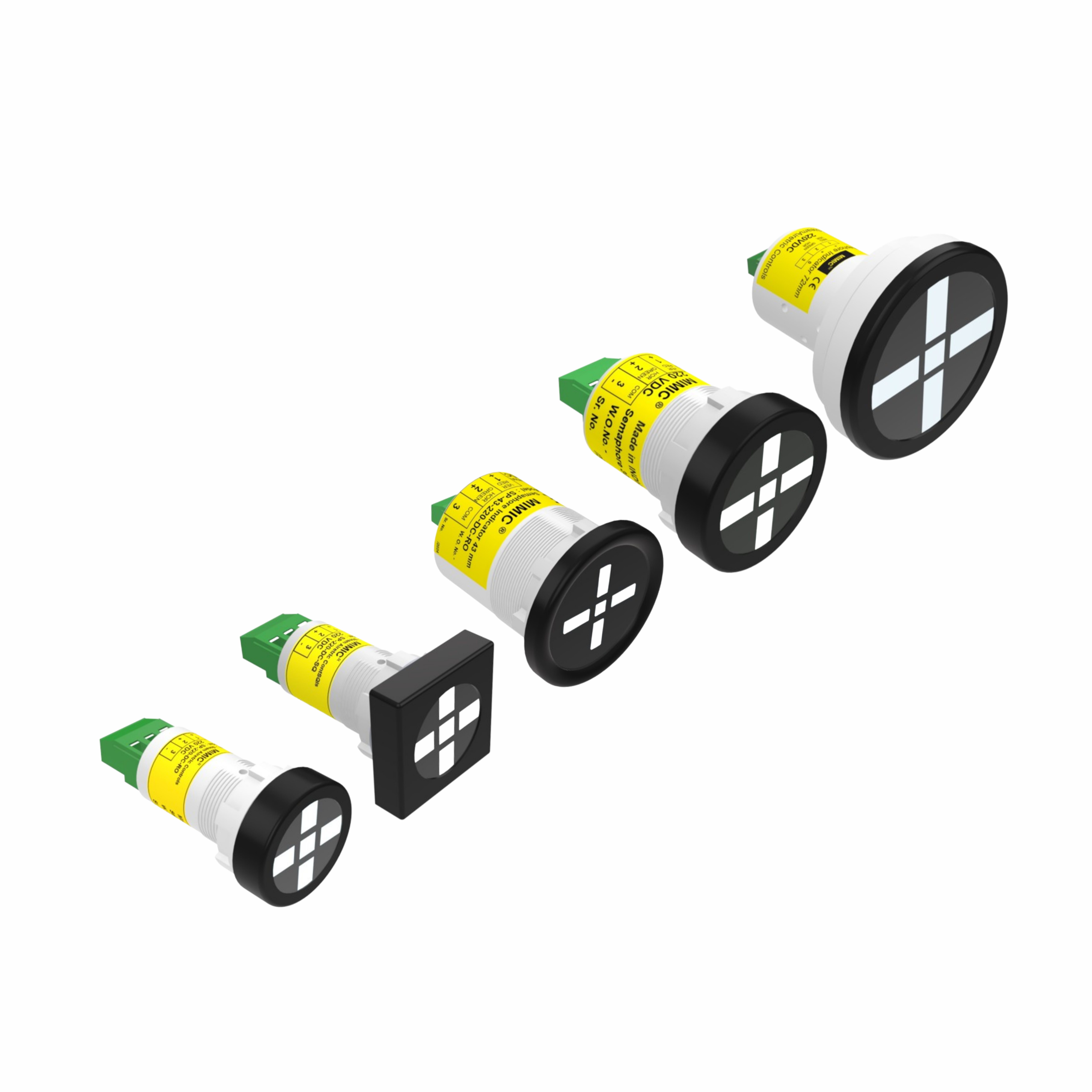
An LED Semaphore Indicator is one component used for this purpose. It provides a visual representation of selected equipment conditions through a directional display, making it suitable for applications involving electrical mimic diagrams. When correctly selected and integrated into an H.T.Panel, it can help operators interpret the status signals associated with circuit breakers, isolators, and other switching equipment.
Understanding the available configurations, electrical ratings, and installation requirements helps panel builders choose a product that fits their design rather than relying on appearance alone.
How Does an LED Semaphore Indicator Work?
A semaphore indicator is a panel-mounted visual signaling device that displays a particular position or status through its visible orientation and colour. It is often used on a mimic diagram, where the indicator corresponds to a specific part of the electrical system.
LED technology provides the illumination required to make the displayed signal visible. Depending on the selected model and its wiring arrangement, the indicator presents the signal assigned to the relevant equipment condition.
The Mimic Products range includes red and green indications, with red displayed vertically and green horizontally in the described configuration. The actual meaning of each indication must be established by the panel's circuit design and operating documentation.
This arrangement helps distinguish displayed states and associate them with the corresponding switching equipment.
The Importance of Visual Indication in an H.T.Panel
High-tension electrical installations require carefully designed control and monitoring arrangements. An H.T.Panel may include several switching devices, each with its own operating status and associated indication requirements.
A properly configured semaphore indicator can support panel monitoring in the following ways.
Clearer Equipment Status Representation
When several circuit breakers and isolators are installed within a distribution system, identifying their displayed positions is an important part of routine monitoring. A directional indicator provides a visual reference associated with the relevant equipment.
This can help operators interpret the information presented on the panel, provided the indication circuit is correctly designed and connected.
More Readable Mimic Diagrams
A mimic diagram represents the electrical system through a simplified visual layout. Indicators placed at relevant points can help personnel relate displayed signals to the corresponding equipment.
Consistent positioning, labelling, and colour conventions are especially valuable when the diagram represents multiple feeders or switching arrangements.
Better Organisation of Panel Information
A panel containing many separate status lamps can become difficult to interpret if its layout is inconsistent. Suitable semaphore indicators can help create a more structured display by providing position-based indications at designated points on the mimic diagram.
The final arrangement should follow the approved panel design and the site's operating conventions.
Support for Routine Inspection
During routine monitoring, personnel can review the available visual indications and compare them with the expected equipment status. Any unexpected indication should be investigated according to established procedures.
Importantly, an indicator only displays the signal supplied by its control circuit. It does not independently verify electrical isolation or confirm that equipment is safe to work on.
Important Specifications to Review Before Purchasing
Selecting a suitable indicator for an H.T.Panel requires checking several technical details. These specifications help determine whether the product will fit the panel and operate correctly with the intended indication circuit.
1. Rated Operating Voltage
The DC voltage must match the supply used by the panel's indication circuit. The LED semaphore indicator range listed by Mimic Products includes options rated at:
-
24V DC
-
48V DC
-
110V DC
-
125V DC
-
220V DC
-
250V DC
Confirm the precise rating of the chosen model before ordering. Voltage compatibility is essential, and the available ratings should not be treated as interchangeable.
2. Panel Cutout Dimensions
Mounting dimensions determine whether an indicator can be installed in the intended panel opening. The referenced range includes 22.5 mm, 30.5 mm, 43 mm, and 72 mm configurations, with round and square designs available for selected sizes.
Before finalising a panel layout, check the manufacturer's dimensions, required cutout, mounting arrangement, and available space around neighbouring components.
3. Display Colour and Orientation
The visible display must correspond to the indication scheme defined for the installation. Red and green signals can help differentiate configured states, while the orientation of the display provides an additional visual reference.
The meaning of each colour and position should be documented clearly so that operators and maintenance personnel can interpret the indication consistently.
4. Environmental Protection
The published product range specifies IP52 protection and an operating-temperature range of approximately -20°C to 60°C. These details should be verified for the specific model being considered.
If the installation is exposed to dust, moisture, or outdoor conditions, assess whether the indicator and the complete panel enclosure meet the site's environmental requirements.
5. Testing and Maintenance
Some models include a test function, which can help personnel check the indication according to the manufacturer's instructions. The availability and operation of this feature should be confirmed before purchase.
Routine inspection should also include checking the visible display, electrical connections, and consistency between the indication and the relevant circuit documentation.
Where Can LED Semaphore Indicators Be Used?
These devices can be considered for various electrical monitoring applications where a visual representation of equipment status is required.
-
Substation control panels: To represent selected switching conditions on a mimic diagram.
-
Circuit breaker panels: To display signals associated with breaker position or operating status.
-
Isolator indication systems: To show the configured status of isolators through the relevant control circuit.
-
Earthing switch arrangements: To display the associated indication where the panel design supports it.
-
Transformer distribution facilities: To help personnel interpret the status information available on the panel.
-
Industrial power distribution systems: To organise visual information about connected electrical equipment.
The suitability of a particular model depends on its specifications and the requirements of the installation.
A Practical Checklist for Panel Builders
Before selecting an LED semaphore indicator, panel manufacturers and electrical contractors can use this checklist:
-
Identify the equipment whose status needs to be displayed.
-
Confirm the available DC indication supply.
-
Select a compatible mounting size and shape.
-
Verify the required colour and display orientation.
-
Review the protection rating and operating-temperature limits.
-
Check wiring compatibility and the associated control logic.
-
Confirm the model-specific technical information before placing an order.
These checks can help reduce fitting issues and avoid mismatches between the indicator and the panel's electrical design.
All installation and wiring work in high-tension systems should be performed by qualified personnel in accordance with applicable standards and approved site procedures.
Explore the LED Semaphore Indicator Range at Mimic Products
For electrical engineers, panel builders, and purchasing teams, comparing technical specifications is an important step when sourcing panel indication components.
Mimic Products offers a range of LED semaphore indicators intended for electrical control panels and mimic diagram applications. The available configurations allow buyers to assess different voltage ratings and mounting requirements against their project needs.
Review the individual model details to confirm voltage, dimensions, display arrangement, and environmental suitability. If the application has specific requirements, verify them with the supplier before selecting a product.
Conclusion
A well-designed electrical panel should communicate equipment status in a way that is easy to interpret. An LED Semaphore Indicator contributes to this objective by providing a directional visual display that can be incorporated into mimic diagrams and suitable H.T.Panel arrangements.
For the best fit, consider the required voltage, mounting dimensions, indication logic, and installation environment together. A careful selection process helps ensure that the indicator matches the intended application and provides the information expected from the panel's status display.
By reviewing product specifications before purchasing, electrical professionals can make informed decisions and develop more organised monitoring arrangements.
Frequently Asked Questions
1. What is an LED Semaphore Indicator used for?
It is used to display a selected equipment position or status through a visual indication, often on a mimic diagram in an electrical control panel.
2. How does it help in an H.T.Panel?
It provides a visual reference for status signals associated with switching equipment, helping operators interpret the information displayed on the panel.
3. Which voltage should I select?
Choose a model whose rated voltage matches the intended indication circuit. Confirm the exact specification before connecting the device.
4. What mounting sizes are available in the referenced range?
The published range includes 22.5 mm, 30.5 mm, 43 mm, and 72 mm configurations. Exact dimensions and shape options should be checked against the individual model.
5. Is an indicator sufficient to confirm a breaker is isolated?
No. An indicator displays a signal from the connected circuit and must not be used as the sole confirmation of isolation. Follow the approved isolation and electrical verification procedures.
6. Where can I check the available models?
Visit the Mimic Products semaphore indicator category page to review product options and compare their technical specifications.
What's Your Reaction?
 Like
0
Like
0
 Dislike
0
Dislike
0
 Love
0
Love
0
 Funny
0
Funny
0
 Angry
0
Angry
0
 Sad
0
Sad
0
 Wow
0
Wow
0