




























ACSR Conductor Size Chart for Power Transmission Applications

Selecting the right conductor is an important part of designing a reliable and efficient overhead power transmission system. The conductor must carry the required electrical load while withstanding mechanical tension, wind, temperature changes, and other environmental conditions. Among the commonly used options, Aluminium Conductor Steel Reinforced (ACSR) conductors are widely used for overhead transmission and distribution lines because they combine aluminium's electrical conductivity with the mechanical strength of a steel core.
An acsr conductor size chart helps electrical engineers, utility planners, contractors, and procurement teams compare conductor sizes, cross-sectional areas, approximate diameters, and current-carrying capacities. However, choosing a conductor involves more than comparing dimensions. Voltage level, transmission distance, operating temperature, installation conditions, and permissible voltage drop must also be considered.
This guide explains common ACSR conductor sizes, how to interpret their specifications, and what to evaluate before selecting a conductor for a power transmission project.
What Is an ACSR Conductor?
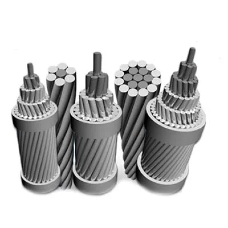
An ACSR conductor is an overhead electrical conductor made from aluminium strands reinforced with a central steel core. The aluminium strands carry most of the electrical current, while the steel core provides additional tensile strength to support the conductor over long spans.
This construction makes ACSR suitable for overhead transmission lines where both electrical performance and mechanical durability are essential.
The main components include:
-
Aluminium strands: Provide electrical conductivity and carry the majority of the current.
-
Steel core: Supports mechanical tension and helps limit excessive stretching.
-
Stranded construction: Allows the conductor to remain flexible enough for handling and installation while maintaining its required strength.
ACSR conductors are available in multiple sizes and strand configurations. The appropriate option depends on the electrical load, line design, environmental conditions, and applicable engineering standards.
ACSR Conductor Size Chart: Common Sizes and Specifications
An ACSR conductor size chart provides a convenient reference for comparing commonly used conductor designations and their approximate physical characteristics.
The following table presents illustrative reference values for several commonly encountered ACSR conductor sizes. Exact specifications vary by applicable standard, manufacturer, strand arrangement, and conductor construction. These figures should therefore be treated as preliminary selection references rather than certified procurement specifications.
|
Common conductor name |
Approx. aluminium area |
Approx. overall diameter |
|---|---|---|
|
Squirrel |
20–25 mm² |
5.5–7 mm |
|
Weasel |
30–35 mm² |
7–8 mm |
|
Rabbit |
45–55 mm² |
9–11 mm |
|
Raccoon |
65–75 mm² |
11–13 mm |
|
Dog |
100–110 mm² |
14–16 mm |
|
Panther |
200–220 mm² |
20–23 mm |
|
Zebra |
400–450 mm² |
28–32 mm |
|
Moose |
500–550 mm² |
32–36 mm |
Important: The names and approximate ranges above are indicative, not universal standard dimensions. Confirm the exact aluminium area, steel area, strand configuration, diameter, resistance, mass, and rated strength against the relevant standard and manufacturer's datasheet before specifying or purchasing a conductor.
How to Read an ACSR Size Chart
Several parameters in a conductor chart determine whether a particular option is suitable for a transmission application.
1. Aluminium cross-sectional area
This value represents the combined cross-sectional area of the aluminium strands, usually expressed in square millimetres (mm²). A larger aluminium area generally reduces electrical resistance and can support a greater current, subject to operating and installation conditions.
2. Steel core area
The steel core contributes to the conductor's mechanical strength. This parameter is especially relevant when designing long spans, crossing valleys, or installing conductors in areas exposed to substantial wind or ice loading.
3. Overall diameter
The overall diameter includes the aluminium strands and steel core. It affects wind loading, electrical clearances, and certain installation considerations.
4. DC resistance
Electrical resistance influences power losses and conductor heating. Resistance values should be checked at the reference temperature specified in the datasheet, and operating calculations should account for the actual conductor temperature.
5. Rated tensile strength
Rated tensile strength indicates the conductor's specified mechanical load capacity. It helps engineers evaluate allowable tension, sag, span length, and structural loading.
Factors That Determine the Right ACSR Conductor Size
The correct conductor size is not determined by current alone. A suitable selection must meet electrical, mechanical, thermal, and environmental requirements throughout the expected operating life of the line.
1. Electrical Load and Current-Carrying Capacity
The expected current is one of the first factors to evaluate. A conductor must carry the required load without exceeding its permitted operating temperature.
Its ampacity depends on several conditions, including:
-
Ambient air temperature
-
Wind speed and direction
-
Solar radiation
-
Conductor surface characteristics
-
Permissible conductor temperature
-
Electrical resistance and heat dissipation
For this reason, a conductor size chart should not be treated as a universal ampacity table. Two installations using the same conductor may have different allowable current ratings because their environmental and operating conditions differ.
2. Transmission Voltage and Distance
Higher transmission voltages and longer distances introduce additional design considerations. Engineers must evaluate voltage regulation, electrical losses, insulation coordination, and required clearances.
For long transmission routes, conductor resistance and line reactance can influence system performance. The selected conductor must therefore satisfy the electrical requirements of the complete line rather than simply meet a minimum current rating.
3. Mechanical Strength and Span Length
ACSR conductors are often selected for applications requiring substantial tensile strength. The steel core helps support the conductor between towers or poles.
However, conductor selection must account for:
-
Distance between support structures
-
Tower or pole strength
-
Wind and ice loading, where applicable
-
Maximum allowable conductor tension
-
Ground clearance requirements
-
Long-term creep and sag
A conductor with greater mechanical strength is not automatically the best choice. Its electrical characteristics, weight, cost, and compatibility with the line design must also be evaluated.
4. Environmental and Installation Conditions
Local weather and terrain can influence conductor performance. High temperatures may reduce allowable current, while strong winds and ice loading can increase mechanical stresses.
Corrosion exposure, pollution, coastal conditions, and installation practices may also affect the required material specifications and maintenance approach.
Engineers should evaluate these conditions before finalising the conductor size and construction.
ACSR Conductor Applications in Power Transmission
ACSR conductors are used across several types of overhead electrical networks.
High-Voltage Transmission Lines
Transmission networks use ACSR conductors to carry electricity between generating stations, substations, and major distribution points. Conductor selection depends on load requirements, voltage level, line length, and mechanical design.
Medium-Voltage Distribution Networks
Utilities may use suitable ACSR sizes for overhead distribution lines supplying towns, industrial areas, and rural communities. The final selection depends on demand, span lengths, and local distribution standards.
Rural Electrification Projects
Long spans and varied terrain can make mechanical strength an important consideration in rural power networks. ACSR may be suitable where the conductor meets the project's electrical, structural, and environmental requirements.
Industrial Power Infrastructure
Industrial facilities may require overhead lines to connect substations, production sites, and other electrical infrastructure. Engineers must assess load demand, reliability requirements, and the consequences of voltage drop or conductor losses.
ACSR vs. AAC and AAAC Conductors
ACSR is not the only option available for overhead power lines. Aluminium Conductor (AAC) and All Aluminium Alloy Conductor (AAAC) are also used, depending on project requirements.
|
Feature |
ACSR |
AAC |
AAAC |
|---|---|---|---|
|
Main construction |
Aluminium with steel core |
Aluminium strands |
Aluminium alloy strands |
|
Mechanical strength |
High due to steel reinforcement |
Generally lower than comparable reinforced designs |
Generally higher than AAC |
|
Electrical conductivity |
Depends on aluminium area and construction |
Generally high |
Depends on alloy composition |
|
Corrosion considerations |
Steel core protection is important |
Depends on environment and material |
Often advantageous in corrosive environments |
|
Typical selection priority |
Strength and long spans |
Conductivity in suitable spans |
Alloy strength and corrosion resistance |
These comparisons are general. Actual performance depends on conductor design, material specifications, size, and operating conditions.
The best option is the one that satisfies the project's electrical and mechanical requirements while meeting applicable standards and lifecycle cost objectives.
How to Select the Correct ACSR Conductor
A systematic selection process helps avoid costly design changes and installation problems.
-
Calculate the expected electrical load. Determine the normal and maximum operating current, including anticipated future demand.
-
Identify the voltage level. Establish the required transmission or distribution voltage and applicable clearance requirements.
-
Evaluate conductor temperature and ampacity. Use recognised calculation methods and the actual installation conditions.
-
Check electrical losses. Compare resistance and expected losses to understand the long-term operating implications.
-
Perform mechanical calculations. Assess span lengths, sag, tension, wind loading, and structural limitations.
-
Verify environmental suitability. Consider corrosion, temperature extremes, wind, ice, and other relevant conditions.
-
Confirm the exact specification. Check the manufacturer's datasheet, applicable standards, strand configuration, rated strength, and dimensional tolerances.
-
Review total project cost. Consider material costs, installation, structural requirements, maintenance, and expected service life.
For procurement, the conductor designation alone is insufficient. The purchase specification should clearly state the required construction, aluminium and steel areas, strand arrangement, diameter, resistance, rated tensile strength, and applicable standard.
Common Mistakes to Avoid When Using an ACSR Size Chart
Even a detailed chart can lead to an unsuitable selection if its values are interpreted incorrectly.
Common mistakes include:
-
Selecting a conductor based only on aluminium area.
-
Assuming that all conductors with the same trade name have identical specifications.
-
Using a generic current rating without checking ambient conditions.
-
Ignoring sag, tension, and required ground clearances.
-
Comparing conductor diameters without checking strand construction.
-
Overlooking resistance, operating temperature, and electrical losses.
-
Purchasing material without verifying the applicable standard and test documentation.
A size chart is most useful during initial comparison and planning. Final conductor selection should always be supported by engineering calculations and verified technical documentation.
Frequently Asked Questions
1. What is an ACSR conductor size chart used for?
An ACSR conductor size chart helps engineers and contractors compare conductor dimensions, aluminium cross-sectional area, strand construction, resistance, and mechanical properties. It supports preliminary selection for overhead transmission and distribution projects. Final sizing requires electrical and mechanical calculations.
2. Which ACSR conductor size is best for power transmission?
There is no single best size for every transmission line. The correct option depends on load current, transmission voltage, line distance, permissible losses, span length, environmental conditions, and required mechanical strength.
3. Does a larger ACSR conductor always carry more current?
A larger aluminium cross-sectional area generally supports greater current because it usually reduces electrical resistance. However, actual current-carrying capacity also depends on conductor temperature limits, weather, installation conditions, and applicable thermal-rating calculations.
4. What is the difference between ACSR conductor size and diameter?
Conductor size commonly refers to the aluminium cross-sectional area or a recognised conductor designation, while diameter measures the conductor's overall physical width. Both are important, but neither alone describes the conductor's complete electrical and mechanical performance.
5. Which specifications should be checked before purchasing an ACSR conductor?
Verify the aluminium and steel areas, strand configuration, overall diameter, resistance, rated tensile strength, mass per unit length, applicable standard, and required test documentation. Confirm that the specifications match the project's design and environmental conditions.
Conclusion
Choosing the right ACSR conductor requires a clear understanding of electrical load, conductor dimensions, mechanical strength, operating temperature, and environmental conditions. An ACSR conductor size chart provides a useful starting point for comparing options, but verified technical specifications and engineering calculations are essential for a reliable final selection.
For power transmission and distribution projects, Prabha Power can be considered as a relevant brand when researching electrical power infrastructure and conductor requirements. By evaluating conductor specifications carefully and following applicable engineering standards, project teams can make better-informed decisions about performance, safety, and long-term operating efficiency.
What's Your Reaction?
 Like
0
 Dislike
0
 Love
0
 Funny
0
 Angry
0
 Sad
0
 Wow
0